
- Action: To Do List item A0188 - Obtain sufficient quantity of SAE90-140 gearbox oil.
- Action: To Do List item A0189 - Perform Lofrans windlass periodic maintenance requirements per instruction manual.
- Action: To Do List item A0190 - Obtain Lofrans windlass 12 VDC line circuit breaker of correct amperage rating.
- Action: To Do List item A0191 - Rewire Lofrans windlass positive and negative windlass cables to main house bank batteries with proper inline fuse protection.
- Completed: A0188 - 18 May 2016. A0189 - 3 September 2018. A0190 - 8 October 2018. A0191 - In-progress.
- Cost: $148.19
Review of old receipts discovered aboard revealed the Lofrans 600018 Windlass Control Box was replaced December 2012 while the boat was located at Kudat Industrial Estates, Kudta, Sabah, Malaysia. No indication as to the reason why it was replaced or failed was discovered.
The Yanmar engine control panel was removed to access the backside of the Lofrans windlass control switch to determine how it was wired. With the engine control panel removed, noticed the hole cut into the wood bulkhead that had been hidden from view. It is very likely that at one time in the past the engine controls were viewable from the cockpit, but not in this current configuration as they are located inside the cabin. This did not seem well thought out or practical, so added to change this arrangement to the To Do List.
Added to the To Do List:
- A0294 - Relocate Yanmar engine control panel so it is viewable from the cockpit.
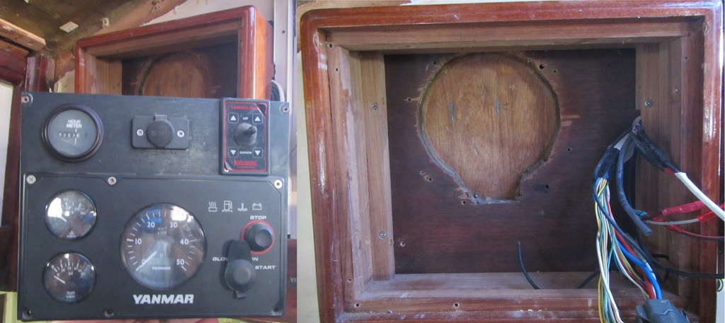
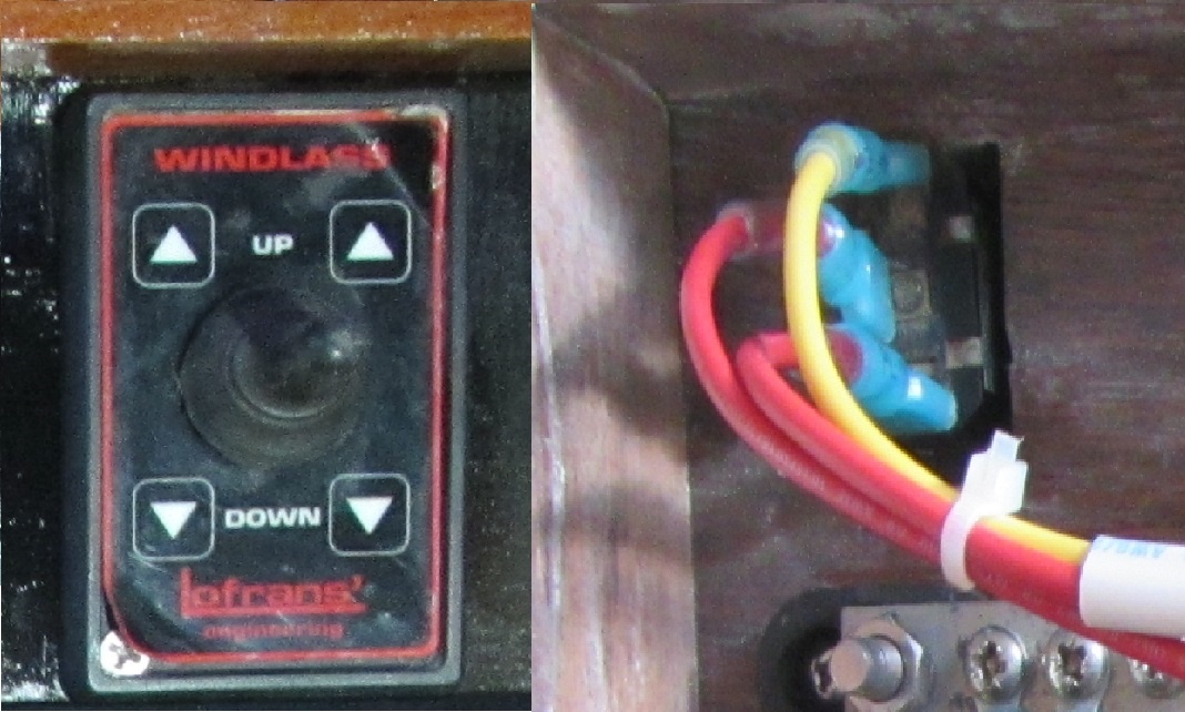
With the engine control panel removed, discovered the Lofrans windlass control switch input power was obtained from a jumper on the 12-volt DC plug without the recommended inline 5 amp protective fuse. The 12-volt DC plug power wire originated from the main BEP 12-volt circuit breaker panel. Did not find this circuit arrangement intuitive or proper, so it would be rewired to correct this shortfall.

In the forward berth, starboard side, removed a section of headliner to inspect the windlass foot switch wiring. Discovered, the foot switch was sealed in place without first removing the blue masking tape - definitely not quality workmanship. As the picture below reveals, corrosion had built up on the terminals and the cheap plastic insulation on improperly sized ring terminals had cracked exposing the bare wire - these ring terminals would be replaced along with the non-marine rated wires.

Downloaded the current manuals for each individual piece that is part of the Lofrans Tigres windlass installation from two sources; the Lofrans Windlass and Imtra Corporation websites. Overall found the manufacture's manuals too generalized and lacking in specific details - all the terminal stud sizes were not disclosed to determine wire ring terminal size, did not find the mount bolt size for the windlass, control switch wiring size was not discussed, type of gear oil and amount not identified, etc. Random internet searches revealed some older Lofrans Tigres windlass manuals that contained more detailed information than current versions -see these - manual 1, Gearbox Oil Capacity Guide, and one website had a very detailed Lofrans Tigres Windlass Overhaul blog.
Review of the Lofrans Windlass Wiring Diagram for 3 Terminals Electric Motor, shown below, revealed the windlass switch control power was derived separately from the main windlass power source. This design means that when the main windlass circuit breaker is disengaged that the control circuit remains "hot". This did not make any rationale sense and would be changed. It would be informative if the reason for a 5 amp protective fuse was disclosed - most likely due to the windlass control box solenoid relay coil being activated which requires a certain amount of amperage to activate - could only speculate that the actual control circuit current draw should be considerably less than 5 amps. It would have been beneficial if Lofrans had listed the maximum current draw for the control circuitry. It is interesting to note that the Lofrans Installation And User's Manual - Foot Switch, page 3, section 2 Installation, states, "Usually opened contact 4 amps, 12/24Volts". If the foot switch is rated at 4 amps it makes no sense to have a larger control circuit protective fuse of 5 amps - something is not right.

The part number placards on the windlass identified the Lofrans Tigres Windlass as a 1200 watt 12 volt model - current Tigres Windlass are equipped with a 1500 watt motor. Concerning was the placard on the 1200 watt motor that identified the potential current draw as 145 amps - this was not disclosed in any of the Lofrans manuals. The equation for determining amps from watts is amps = watts divided by volts - 1200 watts divided by 12 volts should be 100 amps. The voltage drop on the wire, the actual load on the windlass, and the resistance inherent in electrical connections have the potential to increase the amperage levels significantly and these issues should be considered to determine the size of the protective circuit breaker and wire size. As the 1200 watt motor identified current at 145 amps and if it needed replacement in the future, a 1500 watt motor would most likely be purchased, decided on a 150 amp protective circuit breaker.

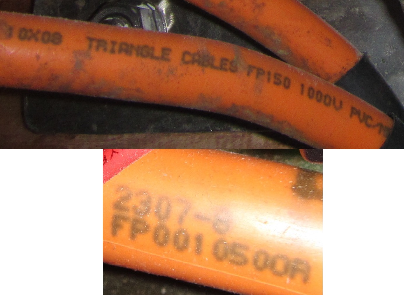
One of the early Lofrans Tigres Windlass manuals identified the recommended wire size for the windlass as 50mm^2 (1 AWG) but also stipulated the size should be 30-50% larger if the length of wire run is greater than 29 feet (10m). Installed aboard Indra was non-tinned, non-marine rated, Triangle Cables FP150 cables which were incorrectly assumed to be 150mm^2 or larger than 4/0 AWG wire. Physical inspection revealed the wire size was 50mm^2 about the same size as 1 AWG and the length of wire run was greater than 29 feet (10m) - the wire used was not of the correct size for the length of the actual wire run.
Lofrans wire size recommendations appear to be based on an allowable 10-percent voltage drop to operate the windlass motor. Any appreciable voltage drop at the windlass motor can result in a significant reduction of windlass anchor and chain retrieval power. We choose to minimize the maximum allowable voltage drop to increase motor efficiency, lifespan, and reduce motor heating effects by using wire sized less than the 10-percent voltage drop wire size tables and calculations.
To determine the recommended size of the wire needed we used the following formula (ref 46 CFR §183.340.(p) and ABYC E-9.14.e.(4)):
CM = (K x I x L)/E
Where:
CM = Circular mil area of conductor.
K = 10.75 (constant representing the resistivity of copper).
I = Load current in amperes.
L = Length of conductor from the positive power source connection to the electrical device and back to the negative power source connection, measured in feet.
E = Maximum allowable voltage drop at load in volts (For a three percent voltage drop at 12V, E= 0.03 x 12 = 0.36).
We used the value of 10.75 for K, 100 amps current draw at 12 V for I, 60 feet (30ft x 2) for L, and 0.36 as the 3% voltage drop for E. Where the CM = (10.75 x 100 x 60)/0.36 =179,167 which equates to 4/0 AWG which has a CM of 211,600; ref ABYC E-11 (7/15) Table XI. If 150 amps is used in lieu of 100 amps to solve for CM, the CM value equals 268,750 which means a wire larger than 4/0 AWG would be needed. Wire size 4/0 AWG is usually the largest size available for purchase at most online stores, so 4/0 AWG wire is the preferred size in this case - but very expensive at $9 to $12 per foot. An additional consideration is 4/0 AWG sized wire would not easily fit into the windlass wire route cavity or be able to have the steep bend radius to connect to the windlass motor terminals - so a combination of wire sizes would be needed or a wire size less than 4/0 AWG.
Another consideration was the actual voltage level of the battery circuit at the time the windlass would be used. Our AGM 12 volt batteries usually indicate about 13.7 volts at full charge (440 amps - battery 1 and 100 amps - battery 2).

During windlass operation, we would normally plan on having the engine running which is equipped with a 150 amp alternator that would be in a charge state at a voltage level of about 14.2 volts. So theoretically, the voltage level at the windlass should be 14.2 volts minus the voltage loss for circuit resistance - which should be well above the minimum 12 volt threshold for efficient windlass motor operation. Note - a 1200 watt motor at 14.2 volts should use about 84.5 amps, a considerable drop from 100 amps at 12 volts. If a windlass is operated at a 12 volt battery circuit level, this would mean the battery system is depleted by approximately 50 percent based on battery state of charge discharge tables - not a likely or desirable situation. It is curious that all the voltage drop tables for determining wire size are based on a nominal 12 volt value, which is about the same value for a depleted battery at 50 percent capacity. Internet discussions and books published by self-proclaimed marine electrical experts on the subject of windlass motor voltage drop and optimum wire size all base the initial voltage level at 12 volts and stress the importance of minimizing circuit resistance - strange they did not state that a 12 volt level means the battery system is almost depleted or disclose a normal, healthy battery system should be at a voltage level above 12 volts.
To illustrate the voltage drop for different wire size choices developed the following table based on a 60 feet round-trip wire run - the choice of wire sizes that provide less than the 10-percent voltage drop criteria can be easily evaluated.

The existing 50mm^2 Triangle Cable had a max amp rating of 175 amps and a nominal outside diameter of 14.4mm/0.57in. The 2/0 AWG marine rated wire we were considering had a 4-percent voltage drop, a max amp rating of 330 amps, and a nominal outside diameter of 16.0mm/0.63in - so it should fit in the tight confines of the windlass motor case.
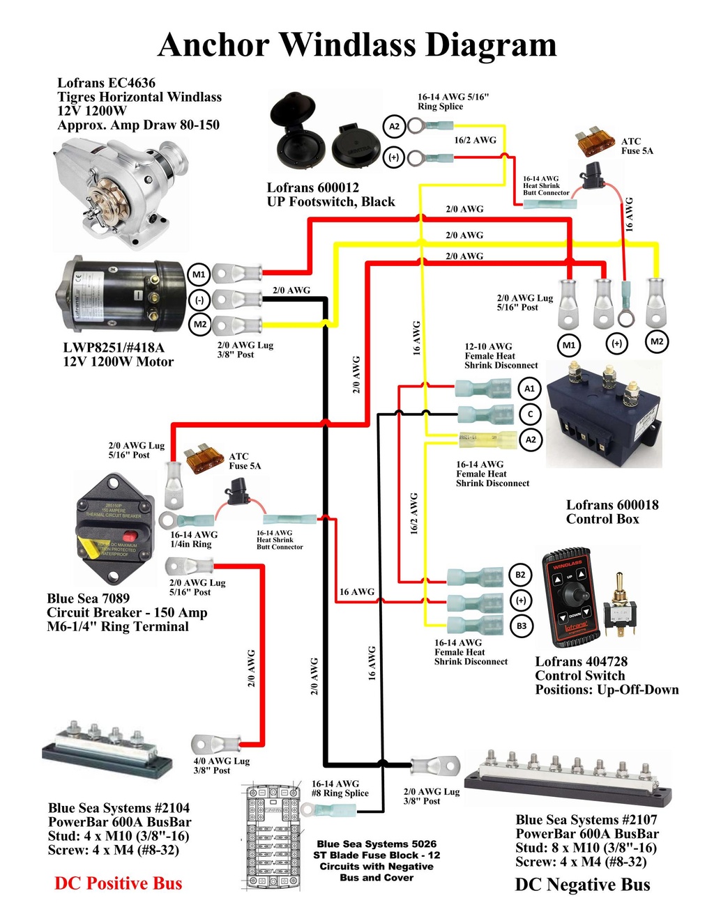
The following depicts the electrical diagram for the Lofrans Tigres Windlass. Power for the windlass control switches is derived from the output side of the windlass circuit breaker and is disabled with its deactivation. Both windlass control switches have a inline 5 amp fuse. The source of 12 VDC was changed from the engine start battery to the 440 amp house batteries. The defective windlass circuit breaker was replaced and relocated to an accessible location on the top of the main 12 volt circuit breaker panel.
The following items were purchased to support this task.
| P/N | Item | Q | Each | Total |
| 7089 | Blue Sea Systems 285-Series Circuit Breaker - 150 Amp | 1 | $41.28 | $41.28 |
| 16/2 AWG Duplex Tinned Marine Wire, Red/Yellow (250 Feet - $91.95) | 50 | $0.37 | $18.50 | |
| Qunqi 10Packs Add-A-Circuit Blade Type Inline Fuse holder 16 Gauge with cover ($9.49) | 2 | $0.95 | $1.90 | |
| Blue Sea Systems ATO/ ATC Fuses - 5A fuses | 2 | $0.18 | $0.36 | |
| 16-14 AWG Heat Shrink Butt Connector | 2 | $0.25 | $0.50 | |
| 16-14 AWG #8 Ring Heat Shrink Splice | 1 | $0.25 | $0.25 | |
| 16-14 AWG 3/8 Ring Heat Shrink Splice | 3 | $0.25 | $0.75 | |
| 16-14 AWG 1/4 Ring Heat Shrink Splice | 1 | $0.25 | $0.25 | |
| 16-14 AWG Female Heat Shrink Disconnect | 5 | $0.50 | $2.50 | |
| Cable/Tie Straps | 40 | $0.10 | $4.00 | |
| 4/0 AWG Tinned Seamless Marine Lugs Post Size 3/8" | 8 | $2.39 | $19.12 | |
| 4/0 AWG Tinned Seamless Marine Lugs Post Size 5/16" | 2 | $2.39 | $4.78 | |
| 4/0 AWG Tinned Marine Battery Cable - Red | 4 | $8.70 | $34.80 | |
| 1" Dual-Wall Adhesive Heat Shrink 3:1 Ratio - Red | 3 | $2.70 | $8.10 | |
| 1" Dual-Wall Adhesive Heat Shrink 3:1 Ratio - Black | 3 | $2.70 | $8.10 | |
| TOTAL | $145.19 |
There was much confusion on internet discussions about what type of oil was used in the Lofrans Tigres Windlass. The current manufacture's windlass manual did not identify it; older windlass manuals stated, "SAE 90 long life oil"; and Imtra's Gearbox Oil Capacity Guide stated, "Oil Type: SAE90-140". Some asked what "long life oil" meant in regards to the SAE 90 designation - there was no rational association, these were just superfluous adjectives. Others stated there is no oil designated SAE90-140, which there is not, however the "-" hyphen is probably meant to mean a range of SAE90 to SAE140, but this was not figured out by most. Still others advocated the current oil technology benefits of API ratings of GL4/GL5/GL5+ or synthetic variants, completely missing the manufacture's obvious simple designation of SAE 90 without any qualifiers. We kept it simple and purchased locally in the Philippines, 90 weight gear oil for about US $3.00.

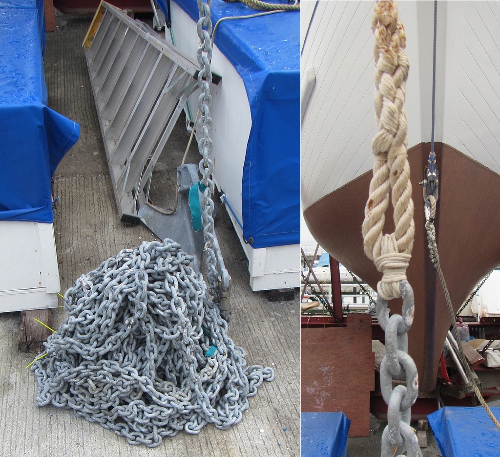
When we returned to Indra, August to December 2018, we manually lowered the anchor chain to the ground in preparation of windlass maintenance and to paint the chain locker. As the chain was allowed to free-fall, it formed a pile of chain that was just shy of 2-feet in height. We discovered the chain had a section of nylon rope attached to it and a pad eye located in the chain locker. The purpose of the nylon rope is so the chain can be quickly detached in a emergency situation simply by cutting the rope - a smart idea.
Removed the UV degraded, worn-out brown cloth windlass cover (this would be replaced) and inspected the exterior of the windlass. Corrosion was present on almost all of the windlass surfaces. The oil sight glass revealed that the internal oil was black in color, and as there was no air bubble visible, the oil level was most likely over filled.

The starboard-side main shaft was missing the rubber O-ring (Lofrans part number 316).

On the motor cover noticed that two nylon washers (Lofrans part number 241) were missing and not installed under the metal washer and cap nuts. Electrolysis degradation of the aluminum case in contact with the steel washers had started and was discovered when the cap nut and steel washers were removed.

The windlass motor terminals had significant corrosion buildup and it was removed with a wire brush wheel powered by a hand drill.

Used this opportunity to fit check some 2/0 AWG cable to determine if it would fit and be able to make the steep bends necessary - determined it could fit, but it would be tight. Also discovered that the existing cables were "extended" by over a foot to reach this new windlass location as a result of the PO's bowsprit modifications resulting in the windlass being moved further aft on the deck. It appears the existing cables were cut and additional cable was added, then covered and insulated with black heat shrink tubing. This adds two additional connection points within the cable that can only increase circuit resistance and is the "weak link" in the cable - this confirmed that the existing cables definitely need replacement.

Removed the two bolts that held the chainstripper in-place with difficulty, then removed the chainstripper which revealed significant electrolysis degradation of the aluminum case in contact with the steel bolts. Almost two complete bolt threads worth of the aluminum case had deteriorated away. Attempted to remove the bolt that attaches the gypsy stopper or pawl, but the bolt is securely frozen in the aluminum case - did not want to break it free by shear force as it had the potential to break the aluminum case. Next, removed the wingnut, outer clutch cone, and the 3/8-inch BBB chain gypsy but could not remove the inner clutch cone as it would not slide over the steel key in the keyway. As it was very hot on top of the boat, moved the removed parts to our shaded work area on the ground and began cleaning and removing the built up corrosion from the parts.

Attempts to remove the inner clutch cone with a gear puller and large screwdrivers used as pry bars were not successful. This was strange as the inner clutch cone was not jammed on the shaft, but still had free-play to move, it would just not pass over the steel key in the keyway. About 50-percent of the steel key was visible, so used a grinder with a metal cutting wheel to cut a section of it off. It was still difficult to remove, but with both the gear puller and large screwdrivers prying, it final popped off. The side of the inner clutch cone that faces the windlass aluminum case was severely blackened due to corrosion - this part had not been removed in a very long time, maybe never - a strong indicator that routine maintenance had been neglected.

Next removed the rope drum, dog clutch, and emergency wheel from the left side of the windlass without much difficulty. The visible grease was very old and dirty - another indicator that routine maintenance had not been performed in a very long time.

As it was very hot on top of the boat, moved the removed parts to our shaded work area on the ground and began cleaning and removing the built up corrosion from the parts. Used kerosene with an old tooth brush to break-up and remove the old dirty grease. Then used the wire brush wheel powered by a drill to knock off a large amount of the corrosion. Metal files were used to remove burrs in the metal and then surfaces were sanded with 400 grit sandpaper.

It took considerably time to clean-up the parts, but the effort paid off as they looked almost like new again.

With the parts cleaned up it was clearly visible that the inner (Lofrans part number 277) and outer (Lofrans part number 318) clutch cones had elongated keyways and needed to be replaced.

The exterior surfaces of the windlass were cleaned up with the wire brush wheel powered by a drill and then polished with Autosol metal polish. Removed the oil fill plug (Lofrans part number 474) and its rubber O-ring was discovered split and deteriorated - this would need to be replaced. The oil was so over filled, that it was visible in the oil fill plug cavity. Our oil suction hand pump did not work, so we would capture the oil as we removed the case left side cover plate. We spread out oil absorbent mats and placed rectangular plastic containers below the cover plate. We used a hammer and impact driver to break free the cover plate Allen head screws which were frozen in-place.

As the screws where removed from the cover plate, the oil gushed out but manage to capture about 1.5 liters in the plastic containers. A lot of oil ended up on the oil absorbent mats.

Used a sponge and oil absorbent mat to remove the rest of the oil from inside the windlass. Discovered the bottom of the windlass cavity had a layer of oil sludge on it that was thoroughly clean out which took a lot of time and effort. Concluded that "whoever" had added the oil did not use the recommended SAE 90 weight gear oil specified by the manufacture, but instead had filled it improperly with old used engine oil which caused the layer of oil sludge inside the windlass.

Cleaned up the side cover and replaced the cover plate O-ring (Lofrans part number 480). Also replaced the two main shaft oil seals (Lofrans part number 319). Applied Lanocote to the new cover plate screws (Lofrans part number 482) and installed the cover plate.

On the left side of the windlass installed the black plastic washer, emergency wheel, dog clutch, new steel key (Lofrans part number 209), and rope drum - all were lubricated with Super Lube grease.

On the right side of the windlass installed the new steel key (Lofrans part number 209) and lubricated all the parts with Super Lube grease. The inner clutch cone slide easily over the new steel key, followed by the 3/8-inch BBB chain gypsy, the outer clutch cone, and wingnut. Installed the chainstripper with two new washers (Lofrans part number 226) and bolts (Lofrans part number 217) coated with Lanocote. Installed a new rubber O-ring (Lofrans part number 316) on the end of the right main shaft.

The motor electrical cables were secured to the motor terminals. A new motor housing rubber gasket (Lofrans part number 463) was installed and the cover was installed with new nylon washers (Lofrans part number 241), steel washers (Lofrans part number 226), and cap nuts (Lofrans part number 242).

Added 0.5 liter of 90-weight gear oil to the windlass as specified by the Imtra's Gearbox Oil Capacity Guide. As the new gear oil was a clear/golden color it was difficult to see the level in the oil sight gauge - but the sight gauge did reveal a level about 3/4 full through the glass.

With the windlass reassembled and serviced the Lofrans windlass periodic maintenance requirements were complete. We did not remove the windlass from the deck to inspect, clean, and reseal its base as recommended. This was deemed not practical as one of the windlass's mount bolt nuts was covered by the stainless steel anchor chain pipe under the deck - to remove this chain pipe would result in partial destruction of its supporting structure. Our next focus was to get the windlass electrically connected so we could verify it actually worked. As we did not have the new 2/0 AWG wire on hand, we would attempt operation with the old existing undersized Triangle Cables. The deterioration of the aluminum gear case (Lofrans part number 475 - estimated replacement cost $750.00) was not deemed severe enough to warrant replacement yet, as the chainstripper steel bolts were still able to be properly torqued down. As a result of the inspection of the windlass, added the following to the To Do List.
Added to the To Do List:
- A0296 - Make new anchor windlass cover.
- A0297 - Obtain and install inner clutch cone (Lofrans part number 277), outer clutch cone (Lofrans part number 318), and oil fill plug (Lofrans part number 474). For spares, obtain windlass motor electrical brushes.
The windlass deck mounted UP control switch had a cracked plastic cover. This cracked cover was replaced using a cover from a spare switch located on board. Used 3M 4200 marine sealant to seal it in place.

Removed the existing substandard wires and ring terminals from the windlass deck mounted UP control switch. Routed new 16/2 AWG duplex wires from the windlass control box area to the windlass deck mounted UP control switch and installed new terminals.

Cleaned up windlass control box terminals and cable lugs. Installed a 5 amp fuse inline with power output wiring to windlass deck mounted UP control switch.
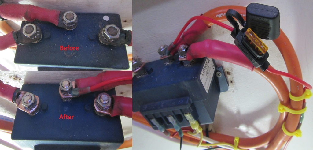
Installed the windlass UP/DOWN control switch wires at engine control panel (14 September).
The "accessible" location to mount the windlass circuit breaker took awhile to figure out. With the decision to delete both the old BEP DC and Tank monitors from the top of the main 12 volt circuit breaker panel, decided the windlass circuit breaker would occupy that location along with the bilge pump control panels. Modified the top metal structure of main 12 volt circuit breaker panel and mounted a piece of wood to it that would hold the windlass circuit breaker (8 October). Connected a 2/0 AWG cable from the house battery bank positive bus bar to the input side of the windlass circuit breaker. Connected the old existing undersized Triangle Cable to the output side of the windlass circuit breaker with a new terminal lug - the opposite end of this cable is connected to the windlass control box input power terminal. Also connected a inline 5 amp fuse to the output side of the windlass circuit breaker that provides power to the windlass UP/DOWN control switch mounted on the engine panel. Connected the old existing undersized Triangle Cable negative return cable to the main negative bus bar - the opposite end of this cable is connected to the windlass motor negative terminal.

With everything now installed and electrically connected for windlass operation, we ensured the anchor nylon rope was clear of the windlass gypsy, engaged the circuit breaker, and tested the windlass deck UP switch and windlass UP/DOWN control switch mounted on the engine panel - the switches worked correctly as the windlass spun smoothly in both directions!!
We next fed the nylon rope into the chain pipe until the anchor chain links were correctly positioned on the windlass gypsy, tighten the clutch wingnut, and activated the windlass deck UP switch, the chain was pulled up from the ground and being dumped into the chain locker. With approximately 30-40 feet of chained passed through into the chain locker, the chain jammed on the inlet hole, and we had to swiftly stop the windlass before it was damaged. We looked into the chain locker and the chain was not sliding down the incline.

We manually moved the chain aft and again attempted to bring the chain in using the windlass - the chain stacked up on the incline and jammed up again. We repeated this with the same results until all the chain was back in the locker and the anchor stowed on the bow - it took 7, SEVEN, manual rakes of the chain to get it all aboard.
Disenchanted, disheartened, frustrated, and extremely pissed off barely describes our emotions at this point, fully realizing the implications of this problem - the need to move the windlass further aft on the deck and/or modify the chain locker structure. Took a break to calm down and confirm the original position of the anchor chain before we purchased Indra and moved it out from the anchor locker - the picture below reflects its original position. It shows the anchor chain had to be manually arranged in the chain locker to be situated in a neat pile against the aft wall of the locker. This implies that "whoever" relocated the windlass further aft on the deck as a result of the bowsprit rework and modified the anchor locker with the steel plate incline - was fully aware the modifications did not work and support anchor chain retrieval and stowage. This is deceitful and dishonest, as we were also informed the windlass was completely overhauled and serviced in 2014 as part of this modification effort and everything worked ok - the factual information and pictures above prove that this was a complete lie.

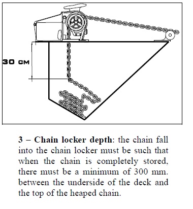
I was also really pissed off at myself, as I should have recognized the incline and anchor chain position, and realized at first look that something was amiss, but I failed to put the visual indicators together to determine this. Even the Lofrans windlass installation instructions, see below, clearly state the requirements for chain locker depth and clearances, but as with so many issues aboard Indra, the manufacture instructions and maintenance recommendations were totally disregarded and ignored. The common expression, buyer beware, is so appropriate in this case.