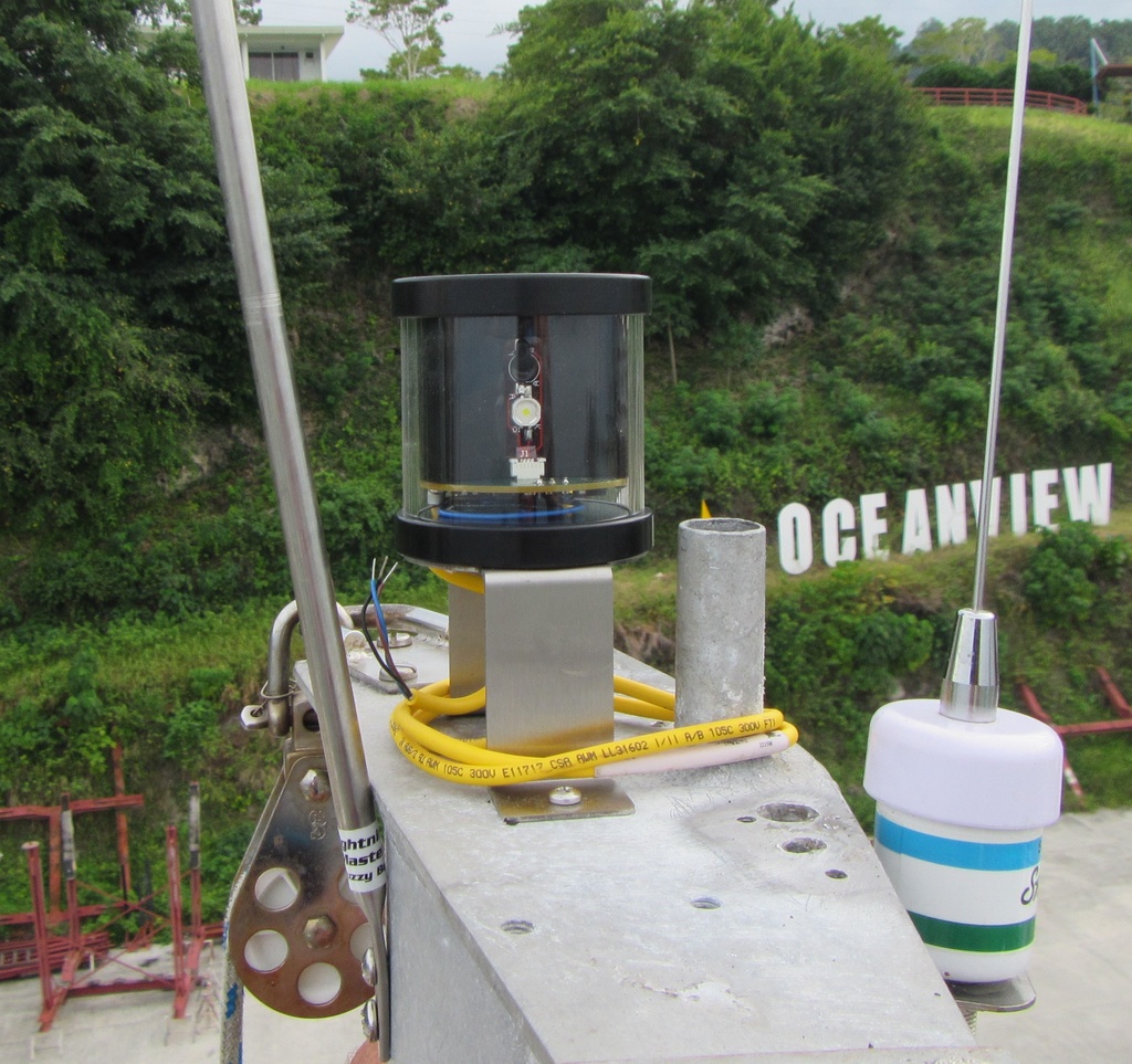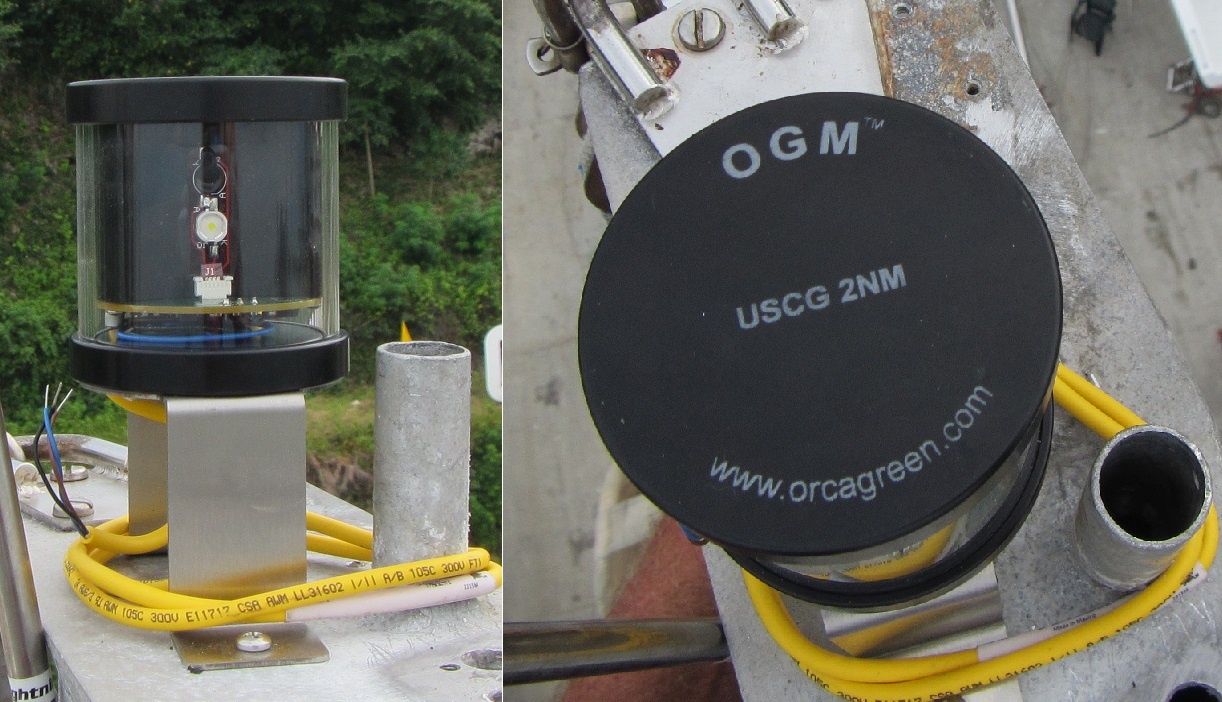

- Action: To Do List item A0029 – Remove all three existing navigational lights at masthead.
- Action: To Do List item A0030 – Obtain and install a single masthead light fixture with Tricolor, Anchor, and Strobe Light functions.
- Completed: A0029 - 12 October 2018. A0030 - In-progress.
- Cost: $550.74
Researched the internet for a single masthead light fixture with tricolor, anchor, and strobe light functions and selected a Orca Green Marine (OGM) model LXTA-SP Tricolor/Anchor combination LED light with daylight sensor and strobe. From the Orca Green Marine (OGM) website downloaded the Orca Green Marine LXTA LED TriAnchor Light Owner’s Manual, bracket drawing, and selector switch diagram.
The pertinent information gleamed from the documentation was:
- Power Consumption: 6 Watts
- Voltage Range: 10 to 28 Volts DC
- Current Draw: 0.33 amps at 12 V
- Wiring: 3-conductor waterproof plug with supplied mating connector and cable
- A circuit breaker or fuse of 2 Amps is recommended.
The OGM specifications seemed inconsistent and incomplete.
- The power consumption identified as 6 Watts equates to a current draw of 0.5 amps at 12.0 volts (Amps=Watts/Volts) which does not agree with the listed current draw of 0.33 amps at 12 volts.
- If the listed current draw is 0.33 amps at 12 volts than the power consumption should be 3.96 watts (Watts = Volts x Amps) instead of the listed power consumption of 6 watts.
- It identifies the wiring as a 3-conductor waterproof plug, but fails to disclose the wire AWG size which is a critical piece of information in planning the installation. It is needed to determine wire splice sizes and wire ampacity limitations.
- The listed 2 amp fuse protection requirement seemed high as the current draw is listed as 0.33 amps - the 2 amp fuse size is six (6) times larger than the expected current draw.
- The listed 2 amp fuse protection requirement could be based on the maximum ampere rating of copper conductors per the National Electrical Code, ANSI/NFPA 70, in this case a 2 amp maximum ampere rating is assigned to 24 AWG size wire.
To install the OGM light new wiring was needed as all the original very old wiring aboard was to be removed. We knew we needed 3 conductors based on the OGM specifications but would have to determine the length and size. We didn't know the exact length, so we estimated - mast height from the cabin top was about 46 feet - rounded to 50; and internal cabin wiring estimated at about 25 feet. So roughly we needed 75 feet of three conductor wiring - a roll of 100 feet would be purchased to provided allowances.
The size of wire in boats is specified and regulated by law as contained in the Code of Federal Regulations (CFR), so a little research is required. It is highly recommended that the Electronic Code of Federal Regulations (e-CFR) be referred to as it is free to access, updated regularly, and "IS" the enforceable law; unlike all the multitude of "how-to" published works - books, magazines, websites, blogs - or personal opinions.
Obtained the following information from the Electronic Code of Federal Regulations (e-CFR):
- 33 CFR §183.425 Conductors: General. Subsections (d) Each conductor in a multiconductor sheath must be at least a No. 18 AWG conductor. (e) Each conductor installed separately must be at least a No. 16 AWG conductor. (f) Each No. 18 AWG conductor in a multiconductor sheath may not extend out of the sheath more than 30 inches. (g) This section does not apply to communications systems; electronic navigation equipment; electronic circuits having a current flow of less than one ampere; conductors which are totally inside an equipment housing; resistance conductors that control circuit amperage; high voltage secondary conductors and terminations that are in ignition systems; pigtails of less than seven inches of exposed length and cranking motor conductors. [Note: 33 CFR §183.401 Purpose, applicability, and effective dates. Subsections (a) This subpart applies to all boats that have gasoline engines, except outboard engines, for electrical generation, mechanical power, or propulsion.] As our boat is equipped with a diesel engine these regulations are not applicable to our situation.
- 46 CFR §183.340 Cable and wiring requirements. Subsections (c) Conductors in power and lighting circuits must be No. 14 American Wire Gauge (AWG) or larger. Conductors in control and indicator circuits must be No. 22 AWG or larger. (d) Cable and wire for power and lighting circuits must:(1) Meet Section 310-13 of NFPA 70 (incorporated by reference; see 46 CFR 175.600) except that asbestos insulated cable and dry location cables may not be used; (2) Be listed by Underwriters Laboratories (UL), as UL Boat or UL Marine cable; [Note: 46 CFR §183.130 Alternative standards. Subsections(a) A vessel, other than a high speed craft, of not more than 19.8 meters (65 feet) in length carrying not more than 12 passengers, may comply with the following requirements instead of complying with the requirements of this part in their entirety: (1) Section 183.420; and (2) The following American Boat and Yacht Council (ABYC) Projects where applicable: (i) E-8, “Alternating Current (AC) Electrical Systems on Boats;” (ii) E-9, “Direct Current (DC) Electrical Systems on Boats;” and (iii) A-16, “Electrical Navigation Lights.”]
So 46 CFR §183.340 provided a choice, use 14 AWG wire as the minimum wire size or comply with the listed ABYC standards. We choose the ABYC standards, in this case, ABYC E-9, Direct Current (DC) Electrical Systems on Boats dated May 28, 1990 incorporated by reference into the CFR; which means it is legally binding and enforceable. Some have advised that we should use ABYC E-11 as it has superseded ABYC E-8 and E-9. While it is advisable to reference ABYC E-11 for potential improved recommendations, ABYC E-11 is not incorporated into the CFR and not legally binding and enforceable.
Obtained the following information from ABYC E-9 dated May 28, 1990:
- E-9.14.b The construction of insulated cables and conductors shall conform with the requirements of SAE 1378, J1127, 11128 or UL1426 "Boat Cable".
- E-9.14.e.(2) Conductors, if used for bilge blowers, electronic equipment, navigation lights and other circuits where voltage drop must be kept to a minimum, shall be sized for a voltage drop not to exceed 3% (see Table VII).
- E-9.16.(h) Conductors shall be at least 16 gauge. EXCEPTION: 18 gauge conductors may be used if included with other conductors in a sheath and do not extend more than 30 inches outside the sheath.
So "by law" the minimum single wire size we can use is 16 AWG and the minimum multi-conductor sheathed cable wire size we can use is 18 AWG - example 18/2 AWG duplex cable.
To determine the actual size of the wire needed we used the following formula (ref 46 CFR §183.340.(p) and ABYC E-9.14.e.(4)):
CM = (K x I x L)/E
Where:
CM = Circular mil area of conductor.
K = 10.75 (constant representing the resistivity of copper).
I = Load current in amperes.
L = Length of conductor from the positive power source connection to the electrical device and back to the negative power source connection, measured in feet.
E = Maximum allowable voltage drop at load in volts (For a three percent voltage drop at 12V, E= 0.03 x 12 = 0.36).
We used the value of 10.75 for K, 0.33 amps current draw at 12 V for I, 150 feet (75ft x 2) for L, and 0.36 as the 3% voltage drop for E.
CM = (10.75 x 0.33 x 150)/0.36 = 1,478.13 which equates to 18 AWG which has a CM of 1,620; ref ABYC E-11 (7/15) Table XI.
However, the power consumption was also listed as 6 Watts which is 0.5 amps at 12 volts. Substituted 0.5 amps for I in the equation and the result was CM = 2,239.58 which equates to 16 AWG which has a CM of 2,580; ref ABYC E-11 (7/15) Table XI.
Based on this we decided to purchase a 100 foot roll of marine-rated 16/3 AWG triplex sheathed cable.
In the OGM Owner's Manual the Wiring section states, "Mast wiring of 20-gauge is sufficient to supply power to the TriAnchor light, although 16 gauge is recommended." This recommendation from the manufacture is not well founded as mast wiring of 20-gauge does not meet wire size regulatory requirements and in our situation is completely wrong advice. As the length of wiring needed for installation on different boats will vary, it is ill advised to provide a recommended wire size. It would have been better to state to the effect, "The use of properly sized marine-grade tinned wire or cable is recommended. The size of the wire for this installation is determined by the total length of wiring required and applicable regulatory guidelines. Consult ABYC E-11 AC and DC Electrical Systems on Boats, regulatory directives, or a certified marine electrician for guidance as needed."
The following items were ordered for this installation:
| P/N | Item | Q | Each |
| LXTA-SP | OGM LED Masthead Photodiode TriColor/Anchor/Strobe Lights | 1 | $377.10 |
| LXBRKT02 | OGM Masthead Light Brackets | 1 | $36.00 |
| SWITCH-SEL | OGM Masthead Wiring Switches | 1 | $44.10 |
| OGM Shipping - US | $15.96 | ||
| OGM Tax - CA | $36.58 | ||
| 16/3 AWG Triplex Tinned Marine Wire - 100 Feet | 1 | $41.00 | |
| TOTAL | $550.74 |
Upon receipt the items were inspected with no damage found, but the individual wires in the yellow cable looked extremely small.

The yellow cable was printed with: "101550642 24 AWG/3 RU AWM 105C 300V E11717 CSA AWM LL31602 I/II A/B 105C 300V FT1 P-07-KA130009-1-MSHA 08915". This identified that the individual wire size was 24 AWG.

Cable Marking Information Decoded:
101550642 - Wire and cable designation by Turck Inc., 5000 Fernbrook Lane, Plymouth, MN 55446. Identification number 101550642 designates cable as 3x24 AWG AWM 2517 105C 300V made to the UL 758 standard. AWM style 2517 identifies wire use as, "External interconnection of electronic equipment or internal wiring of electronic equipment or appliances."
24 AWG/3 - Identifies cable as 3 conductor, with each conductor of 24 American Wire Gauge (AWG) wire size.
RU - UL Recognized Component Mark - Components with this mark are only intended for installation in end products whose safety is evaluated by UL separately, they may be incomplete in construction or restricted in performance capabilities. This means this item is not UL certified, as it does not have the UL Listing Mark.
AWM - Appliance Wiring Material.
105C - Dry temperature rating in degrees Celsius. When used as AWM, intended uses are limited to dry locations at temperatures not to exceed 105°C (applicable to both UL and CSA ratings).
300V - Voltage rating - is the highest voltage that may be continuously applied to a wire/cable per applicable standard or specification.
E11717 - EIS WIRE & CABLE INC, 775 New Ludlow Rd, South Hadley MA 01075-2625 per UL Certification Directory. This is the wire manufacture.
CSA - Canadian Standards Association.
LL31602 - CSA File Number - designated as CSA file number 031602_0_000 and identifies the manufacture as EIS WIRE & CABLE INC. This equates to CSA Class Number 5851-01 which states under section Coverage, "These wires are not for use for connecting to the source of supply of electricity (branch circuits), but may be used for interconnection between pieces of equipment when permitted by a Canadian electrical code."
I/II A/B - CSA AWM Specifications. Class I - internal wiring of equipment. Class II - External/interconnecting wires. Group A - not subject to mechanical abuse. Group B - potentially subject to mechanical abuse.
FT1 - CSA Vertical Flame Test per CSA C22.2 No. 0.3-92 Para 4.11.1.
P-07-KA130009-1-MSHA - Mine Safety and Health Administration (MSHA) flame resistance approval number for mining applications - in consolidated approval list identified as "07-KA130009-MSHA". Indicates cable was tested and accepted as flame-resistant per 30 CFR 7.407.
08915 - Manufacturer Date Code - Day/Year - dddyy.
The 24/3 AWG yellow cable has a straight female M8 threaded picofast connector attached on one end. It is designation as Turck Inc. product PKG 3M-x and described in file number 777000272 drawing PKG 3M-*. This 24/3 AWG cable assembly has a 125 VAC/VDC rating, 4.0 Amp current rating, temperature range of -40C to +105C, and protection class of National Electrical Manufacturer Association (NEMA) Enclosure Ratings of 1, 3, 4, and 6P with International Electrotechnical Commission (IEC) classification of Ingress Protection (IP) 67. It is concerning that per file number 777000272 drawing PKG 3M-* the rated voltage of the cable assembly is 125 VAC/VDC but the cable label markings identify the voltage rating as 300V.
To determine the official requirements for navigational lights the following was obtained from the Electronic Code of Federal Regulations (e-CFR):
Both 33 CFR 183.810 and 46 CFR 25.10-3 Navigation light certification requirements identified the same information.
- 33 CFR 183.810.(2) "Be certified by a laboratory listed by the Coast Guard to the standards of ABYC A-16 (incorporated by reference, see §183.5) or equivalent, .............."
- 46 CFR 25.10-3. (2) "Be certified by a laboratory listed by the Coast Guard to the standards of ABYC A-16 (incorporated by reference, see §25.01-3), or equivalent,.............."
The version of the ABYC Standard A-16, Electric Navigation Lights incorporated into the CFR by reference is dated July 1997. From this version obtained the following:
- A-16.6.7 Navigation lights shall be installed in accordance with ABYC E.8, Alternating Current (AC) Electrical Systems on Boats, or ABYC E-9, Direct Current (DC) Electrical Systems on Boats, as appropriate.
- A-16.8 DESIGN AND CONSTRUCTION REQUIREMENTS paragraph A-16.8.7.1 the wiring shall be in accordance with the applicable requirements of ABYC E-8, Alternating Current (AC) Electrical Systems on Boats, or ABYC E-9, Direct Current (DC) Electrical Systems on Boats.
A reasonable interpretation of these regulations means that "by law" the minimum single wire size is 16 AWG, the minimum multi-conductor sheathed cable wire size is 18 AWG, and the wire insulation must be per type specified by ABYC E-9.14.b. This requirement or law applies equally to wiring installation on a boat and the design and construction of navigational lights. To be in full compliance with the USCG regulations a marine navigational light must also be in compliance with the paragraphs noted above.
The OGM model LXTA-SP Tricolor/Anchor combination LED light, documentation, and advertisements is marked with approvals, "USCG 2NM Approved 33 CFR 183.810 Meets ABYC-A16". The OGM navigational light wiring appears to not comply with USCG regulations for wire size and insulation requirements. The OGM navigational light wire size is 24 AWG which does not meet the wire size requirements of ABYC E-9.16.(h). The OGM navigational light insulation designation is Appliance Wiring Material (AWM) with no UL style identified which does not meet the insulation requirements of ABYC E-9.14.b.
To ascertain these discrepancies sent multiple inquiries on the OGM Contact Us website page, but did not receive a response. Next, posted the same inquiry on the OGM Facebook page, again no response.
Since the OGM LED light was tested and certified to meet USCG standards by Imanna Laboratories, sent an email inquiry to them at info@imanna.com as follows.
Subject: Marine Navigation Light Certification to the ABYC A-16 Standard
Dear Sir/Ma’am,
I have a question on marine navigation light certification to the ABYC A-16 standard as mandated by 33 CFR 183.810.(2) and 46 CFR 25.10-3.(2) which states, “Be certified by a laboratory listed by the Coast Guard to the standards of ABYC A-16 (incorporated by reference……….”.
The ABYC Standard A-16, Electric Navigation Lights, incorporated into the CFR by reference is dated July 1997 and states the following:
- A-16.6.7 “Navigation lights shall be installed in accordance with ABYC E.8, Alternating Current (AC) Electrical Systems on Boats, or ABYC E-9, Direct Current (DC) Electrical Systems on Boats, as appropriate.”
- A-16.8 DESIGN AND CONSTRUCTION REQUIREMENTS paragraph A-16.8.7.1 “the wiring shall be in accordance with the applicable requirements of ABYC E-8, Alternating Current (AC) Electrical Systems on Boats, or ABYC E-9, Direct Current (DC) Electrical Systems on Boats.”
As ABYC E-9, Direct Current (DC) Electrical Systems on Boats, dated May 28, 1990, is also incorporated into the CFR by reference; it states the following in regards to navigational light wiring:
- E-9.14.b The construction of insulated cables and conductors shall conform with the requirements of SAE 1378, J1127, 11128 or UL1426 "Boat Cable".
- E-9.14.e.(2) Conductors, if used for bilge blowers, electronic equipment, navigation lights and other circuits where voltage drop must be kept to a minimum, shall be sized for a voltage drop not to exceed 3% (see Table VII).
- E-9.16.(h.) Conductors shall be at least 16 gauge. EXCEPTION: 18 gauge conductors may be used if included with other conductors in a sheath and do not extend more than 30 inches outside the sheath.
In my opinion, the interpretation of these regulations means that "by law" the minimum single wire size is 16 AWG, the minimum multi-conductor sheathed cable wire size is 18 AWG, and the wire insulation must be per type specified by ABYC E-9.14.b. This requirement or law applies equally to wiring installation on a boat and the design and construction of navigational lights. To be in full compliance with the USCG regulations a marine navigational light must also be in compliance with the paragraphs noted above.
The issue is we purchased navigational lights labeled with approval/certification statements, "USCG 2NM Approved 33 CFR 183.810 Meets ABYC-A16" and the navigational light wiring does not comply with USCG regulations for wire size and insulation requirements. The navigational light wire size was 24 AWG and the insulation designation was Appliance Wiring Material (AWM) with no UL style identified. Per the AWM designation the wire and insulation is to conform to the UL 758 standard.
The wire markings also showed it was Canadian Standards Association (CSA) listed and assigned Class Number 5851-01 which under section Coverage states, "These wires are not for use for connecting to the source of supply of electricity (branch circuits), but may be used for interconnection between pieces of equipment when permitted by a Canadian electrical code."
As the manual identified, “Tested by Imanna Laboratories”, figured the most knowledgeable source for this issue might be you – this is why it was sent to you first. If I have misinterpreted anything contained herein, please advise.
Question?
Does the designation “Approved 33 CFR 183.810 Meets ABYC-A16” mean full or partial compliance with CFR and USCG regulations?
__________________________________________________________________________________________-
Received a response from a IMANNA Lab, Inc. representative, who indicated he referred the inquiry to the company president. After sending a follow up email due to no response on the original inquiry, received the following response:
First, please accept my apology for not getting to this e-mail earlier. I have read your background information and agree with your conclusions; however, I offer some clarifications from the lab and testing side. The certification report states the parameters that are covered in the effort reported. Quite often, we test the light parameters for certification to the Navigation sections of 33 CFR 183 Sub Part M, which does not cover the electrical wiring (33 CFR 183 Sub Part I). Secondly, the electrical conductors in the CFR and in the ABYC standards, refer to the wires outside the device, and do not cover the device design for internal wiring. The pigtail that you see coming out of the device are the device designer's choice to conduct the electricity of his device. The pigtail can be up to 7 inches prior to connection without violating the USCG or ABYC requirements. The pigtail is sized to the demands of the device and the adequate determination is not part of the USCG or ABYC scope. The USCG and the ABYC scope is for connecting conductors between an electrical supply and the device interface. If the designer determines that a very small wire meets the demands of his device, he leaves the connecting conductor design up to the installer and the installer verifies the adequacy of the connection and wire to the 33 CFR 183 Sub Part I and ABYC E-11. This covers the minimum size, strength, and connection pull force up to the device connection. The installer provides the restraint for connecting wires and stress relief from the device.
All of that is to say that I think the wires you have inspected and find suspect, are considered internal device wiring and are not in the scope of the requirements cited. I don't recall seeing the 24 AWG on navigation lights we have certified, but that is not to say that a device like that has never been through our tests. Our comments to customers encourage the designers to provide compliant wire pigtails for the connecting conductors and discourages the use of conductor pigtails that are less than 16 AWG, but we do not dictate the internal wiring unless we find the wiring to be insufficient to accomplish the performance requirements of the CFR or ABYC Standards.
I hope this sufficiently address your question, but if I have fallen short of that please get back to me for further correspondence.
_______________________________________________________________________________________________
Replied to the IMANNA Lab, Inc. email as follows (abbreviated):
First, thank you for responding to my question. No apology is necessary.
I still believe (but could be interpreting this wrong) the light assembly pigtail wiring is not incompliance with USCG requirements due to paragraph A-16.8 DESIGN AND CONSTRUCTION REQUIREMENTS of the light assembly states specifically in paragraph A-16.8.7.1 “the wiring shall be in accordance with the applicable requirements of ABYC E-8, Alternating Current (AC) Electrical Systems on Boats, or ABYC E-9, Direct Current (DC) Electrical Systems on Boats.” As you are aware ABYC E-9.16.(h) states “Conductors shall be at least 16 gauge. EXCEPTION: 18 gauge conductors may be used if included with other conductors in a sheath and do not extend more than 30 inches outside the sheath.” These paragraphs and requirements apply specifically to the design and construction of the light assembly.
Additional standards like the Canadian Standards Association (CSA) electrical code and NFPA National Electrical Code (NEC) 70, both essentially state the same requirements for any appliance or fixture wiring – this LED light assembly would meet their classification as an appliance or fixture. Per NEC 70 paragraph 402.6 Minimum Size. Fixture wires shall not be smaller than 18 AWG. Per NEC 70 paragraph 402.12 Uses Not Permitted. Fixture wires shall not be used as branch-circuit conductors except as permitted elsewhere in this Code. By both these electrical codes, 24 AWG wire pigtails are prohibited from being used in branch circuits (power conductors). Note the minimum approved wire size by both these standards is 18 AWG which is in agreement with USCG and ABYC requirements.
Looking for another standard to reference discovered UL 8750 Standard for Safety for Light Emitting Diode (LED) Equipment for Use in Lighting Products, paragraph 7.4.2.2.1 A field-wiring lead shall be no smaller than 18 AWG (0.82 mm2). Even the UL standard mimics CSA, NEC 70, USCG, and ABYC minimum wire size requirements.
In full disclosure – I purchased Hella Marine NaviLED PRO Navigation lights for port, starboard, and stern running lights and they were labeled with the expected USCG 2NM Approved 33 CFR 183.810 Meets ABYC-A16. The wiring on these lights is 18/2 AWG – which meets regulatory requirements. For the top of the mast I purchased an Orca Green Marine (OGM) model LXTA-SP Tricolor/Anchor combination LED light – its wiring is 24/3 AWG which does not meet regulatory requirements.
The Hella Marine NaviLED PRO Navigation lights LED power consumption was listed as 0.14 amps at 12.0 VDC for each LED light; while the OGM LED light LED power consumption was listed as 0.33 amps at 12.0 VDC for its light. Why did Hella Marine use a larger wire size than OGM, even though their amperage was more than 50% less? I suspect the answer is that one manufacture was familiar with the regulatory and standards requirements, while the other was not.
The following is what was discovered about the OGM LED light wiring. Website links have been incorporated to source the references cited. Abbreviated: Included the section above on OGM cable wire markings and the decoding of that information. Emphasis was put on the following section from above:
LL31602 - CSA File Number - designated as CSA file number 031602_0_000 and identifies the manufacture as EIS WIRE & CABLE INC. This equates to CSA Class Number 5851-01 which states under section Coverage, "These wires are not for use for connecting to the source of supply of electricity (branch circuits), but may be used for interconnection between pieces of equipment when permitted by a Canadian electrical code." [As mentioned above the CSA electrical code, just like the NEC 70 code, stipulates that the smallest size wire approved for branch circuits (power conductors) is 18 AWG.]
In practical application the use of 24 AWG creates additional complications. As the wiring from a power source to the top of a mask (and the ground return back) is probably the longest length of wiring on a boat; to comply with the mandated 3% maximum voltage drop the wire size in most cases will be at a minimum 16 AWG, if not larger. On our boat the 3% voltage drop calculation indicated 16 AWG was acceptable. Problem, there is not a step-down wire splice in the size of 16 to 24 AWG. This means people will get creative devising a substandard method to join the wires – this statement is based on internet forums where the joining of different gauge wires was discussed. In our case, the most viable splice method available is a parallel splice were the wires can lay together – this wire lay together method also provides a means to support the small 24 AWG wire giving it additional mechanical stability. Closure of the splice area is performed by using a heat shrinkable end cap. This splice area will still be the weakest link in the circuit and is exposed to the elements at the top of the mast.
As I desire a definitive answer to this issue, a general inquiry was sent to the USCG Boating Safety Division, Recreational Boating Product Assurance Branch – still waiting for a response from them.
Once again thanks for responding. If you have any feedback on what is stated above, please let me know. No further response was provided.
___________________________________________________________________________________
Researched who at the USCG might be responsible for this issue and sent an inquiry to the USCG Boating Safety Division, Recreational Boating Product Assurance Branch. Currently awaiting a response - no response was provided.
____________________________________________________________________________________
Despite the extremely small 24 AWG wire size, determined a method to complete the installation as depicted in diagram below.
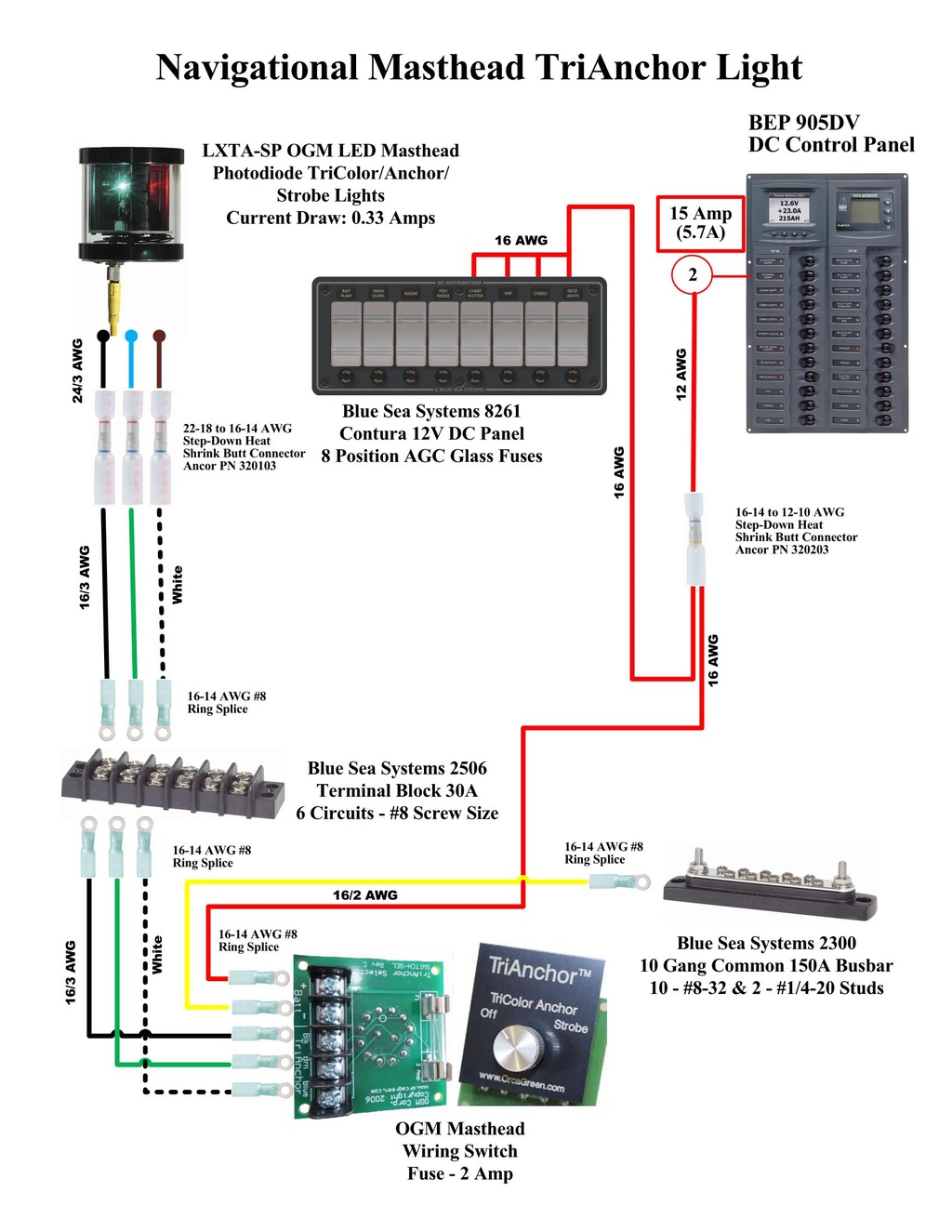
The use of 16-14 to 22-18 AWG step-down butt connector is not ideal as the LED light wire size is 24 AWG. This extremely small wire does not have the mechanical strength of larger size wire, so will need to devise a method to reduce physical stress to the splice location. Doubling the smaller wire over to fit the splice connection or stripping the 24 gauge wire extra long so it goes all the way through the butt connection was considered, but disregarded. The most viable method found was a parallel splice, where one or more conductors of varying gauges can be laid on top of one another and crimped in a short space, then covered with a heat shrinkable end cap.
In April 2018, routed the 16/3 AWG wires from the navigation desk area OGM selector switch to the terminal board located at base of the mast in the head. Power and ground wires were also routed to OGM selector switch.

On 12 October 2018 went up the mast and removed all the old defective mounted hardware. A impact driver and drill were necessary to remove many stuck screws. The three navigation lights were so deteriorated by UV they crumbled and fell apart at the touch.


On 13 November 2018 went up the mast and installed the new OGM Tri-Color LED light assembly. The wire pigtail was not connected but wrapped and stowed at the top.
Next - mast needs to be removed to route internal wiring.