
- Action: To Do List item A0245 - Inspect all light fixtures and wiring. Delete all plastic inline butt splices and solder connections. Connect wiring with crimped/mechanical connections.
- Completed:
- Cost: $
To get access to the overhead LED lights and wiring, four long teak rails, multiple wooden hatch and trim pieces, and all the overhead headliner panels had to be removed. Due to the short-sighted method of their installation, they were not easily removable, and some items were damaged during the removal. As the teak rails and trim pieces were removed, added to the To Do List item B0281, to sand and re-varnish the teak rails and hatch trim pieces.
The defective overhead LED light wiring identified in LED Lights and Wiring page was just the beginning of a much larger issue - the more we looked at the wiring connections the worse and more hazardous the real situation became - it was a prudent decision that we disabled all electrical outputs from the 12 VDC circuit breaker panel to prevent a potential electrical short and fire hazard. The following picture shows a defective solder connection where the soldered power wire (red) became dislodged and was shorted to the return connection - and no, the 15 amp magnetic circuit breaker did not trip. The ABYC and NFPA recommendation of "Solder shall not be the sole means of mechanical connection in any circuit." is fully justified in this example.

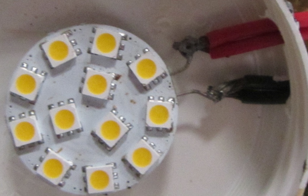
The following picture shows the solder connection was used to improperly connect two wires at the same time it is used to connected the wires to the G4 LED disc terminals.
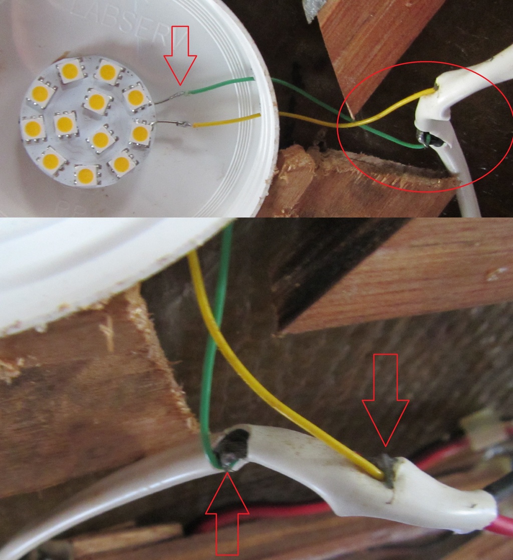
The following picture shows the use of very small, 26 AWG wires, connected to the G4 LED disc terminal and then soldered to the main wire run by "nicking" the main wire insulation and soldering the small wires to the main wire without an insulation cover. This improper style of connecting wires was repeated, again, and again, and again.
The wires used to connect the LED lights were not all the same type. In use were different wire sizes ranging from 16 to 26 AWG and multiple different colors. The following picture shows a red/black pair of wires connected to a short segment pair of white wires by a inappropriate non-marine rated plastic inline butt splice. Both the white and red/black pair of wires lacked any type of wire identification printed on the insulation and therefore are not marine rated. Overall impression of the LED wiring installation appeared to indicate it was pieced together with whatever spare wire segments were available and joined together with excessive use of inline butt splices or connected by solder - it was a very amateurish and incompetent electrical installation.

The following picture shows a nail used to attach a piece of wood trim penetrating a wire splice connection.

When the reading lamp was removed from the bulkhead wall, was no longer surprised to discover the electrical connection was improperly done. The wires were simply twisted together and a dab of solder applied - the green wire connection was left exposed - not insulated, while the black wire had a small piece of black insulating tape applied. Both the green and black wires are suspected to be wires originally installed when Indra was first built. They have no wire identification printed on the insulation, and are 7-stranded thick copper, Type 1 wiring - very stiff. All the original wiring was deleted from use as part of this rework.

As the overhead LED lighting circuit was composed of multiple different branches and operated by different switches, but powered from a single 15 amp circuit breaker, it was discovered that this circuit was wired counter to standard electrical practices. To allow the uninterrupted flow of the positive 12 VDC to all the different switched circuits, the switch action applied a path to ground instead of breaking the positive conductor circuit. (ABYC E-11, 11.12.2.1 - If single pole switches are used in branch circuits they shall be installed in the positive conductor of the circuit.)

The light switch assembly appears to be a New Zealand made, PDL 600-series, switch module, primarily used in residential and commercial buildings. The rear of switch has contacts labeled: C - this was used for the input wire. 1 - this was used for the output wire - both contact C and 1 were connected with the rocker switched to the ON position. 2 - was unused and had a plastic piece covering its entrance - both contact C and 2 were connected with the rocker switched to the OFF position. LOOP - was unused and is not connected to contacts C, 1, or 2 - it is suspected to be used as a point to join separate wires - like a mechanical wire splice. As the picture below illustrates, the set screw for each terminal contact, when tightened, puts pressure directly against the inserted wire. This is counter to ABYC standard E-11, 11.14.3.5 - Connections may be made using a set-screw pressure type conductor connector, providing a means is used to prevent the set-screw from bearing directly on the conductor strands. This recommendation is prudent as the Ground Return Wire depicted in the picture above had its wire strands flattened and had almost completely pulled out of the C contact terminal.

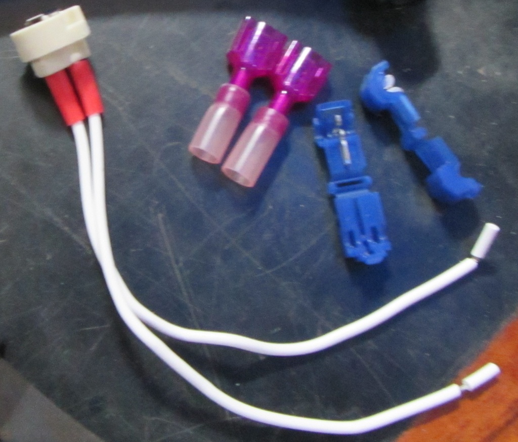
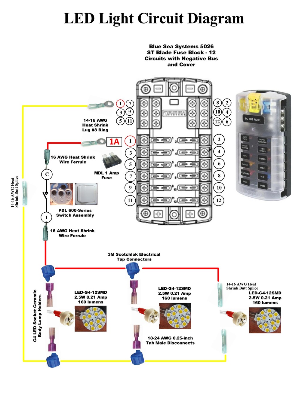
Instead of starting fresh with commercial recessed overhead LED light fixtures (which might have been a simpler and smarter solution - though significantly more expensive), decided to retain the existing plastic lid "fixtures" with G4 LED discs and fix the wiring and electrical connection problems. Use of LED Socket Ceramic Body Lamp holders, 3M Scotchlok Self Stripping Electrical Tap Connectors, and 1/4-inch tab male disconnects would replace all the soldered connections as shown in picture below. Marine rated 16/2 AWG duplex sheathed wiring would replace all the old wiring.
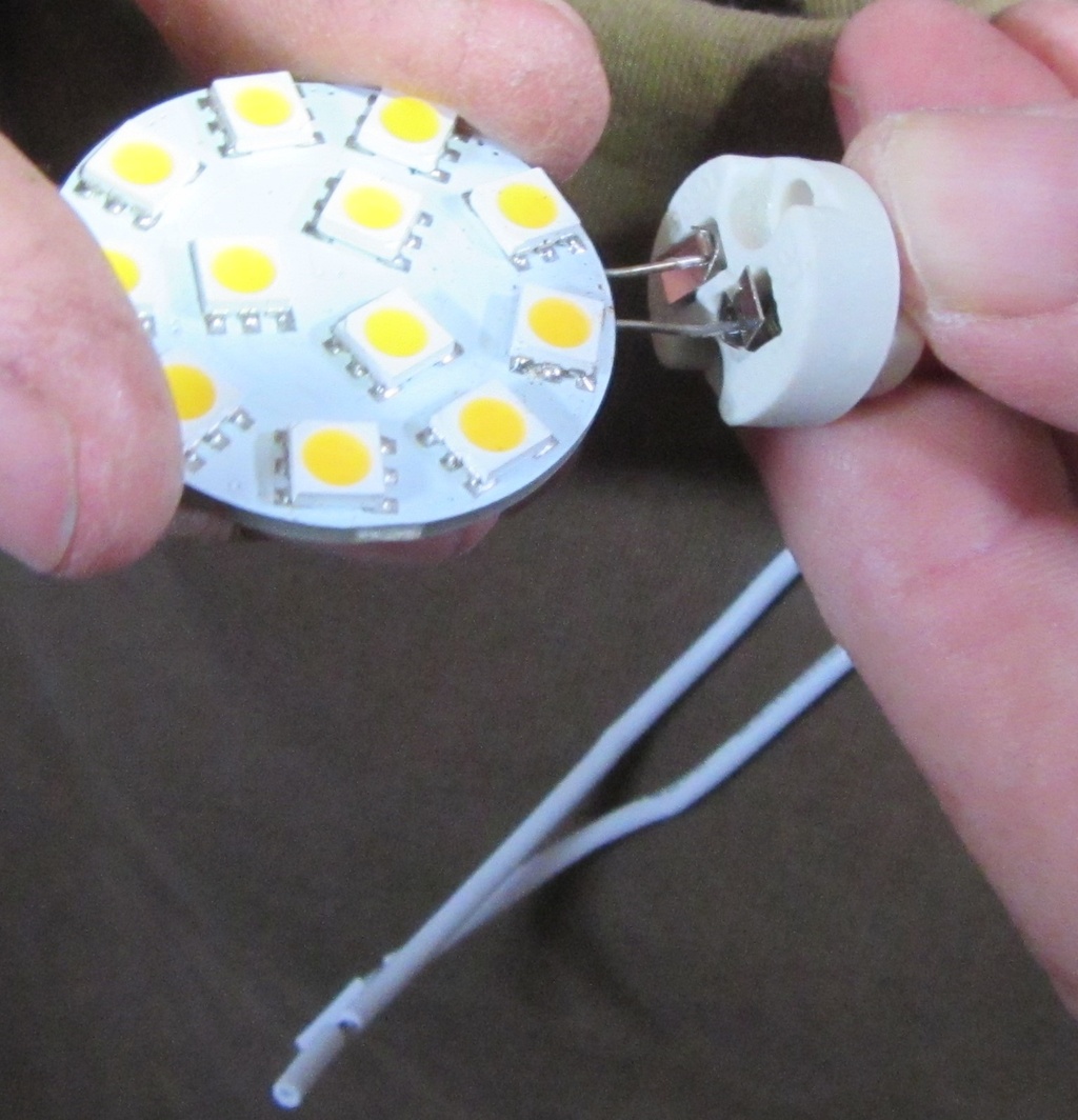
The process was very simple, but took time to accomplish. First the existing G4 LED disc needed to be removed from it's glued in position on the plastic lid and all solder and wires removed from their terminals. The G4 LED disc was then inserted into a ceramic body lamp holder, which securely held it in place with spring loaded metal tabs. Use of this G4 LED disc ceramic body lamp holder also meant in the future the LED disc could be easily replaced if a failure occurred.
The first light fixture in the circuit had the G4 LED disc ceramic body lamp holder wires spliced to the 16/2 AWG duplex wiring with marine rated splices with heat shrinkable insulation.
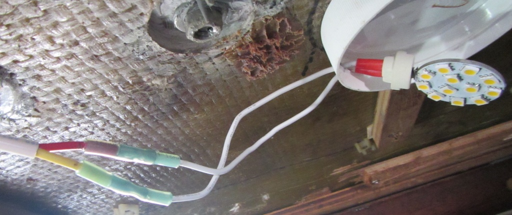
A continuous, unbroken run of 16/2 AWG duplex wiring was routed by each successive LED light fixture to the switch location. The next G4 LED disc ceramic body lamp holder wires had 1/4-inch tab male disconnects installed and these were attached to a small unsheathed portion of the 16/2 AWG duplex wiring with 3M Scotchlok Self Stripping Electrical Tap Connectors as the picture below illustrates. This method resulted in fully sealed and insulated connections; and eliminated all previous improper soldered connections. The G4 LED disc with ceramic body lamp holder was then reattached to the plastic light "fixture" lid with a dab of adhesive sealant only applied to the ceramic body lamp holder - leaving the G4 LED disc easily replaceable.

To correct the discrepancy of the bare wires inserted at the light switch, and compressed by the set screw, the use of wire ferrules with heat shrinkable insulation was used.

The G4 LED disc had a power consumption rating of 2.5 Watts which equates to about 0.21 amps at 12-volts DC. The G4 LED disc ceramic body lamp holder wire size is 0.75mm or just a little smaller than 18 AWG, and had a current rating of 2 amps/100 Watts. The 16/2 AWG duplex wiring had a free air ampacity rating of 22 amps. As there were multiple G4 LED disc lamps in each branched circuit, the protective fuse size of each branched circuit would be a little larger than the sum total of amps consumed by the number of G4 LED disc lamps in that circuit. So, for a circuit with three G4 LED disc lamps (3 x 0.21 amps = 0.63 amps) a protective fuse of 1.0 amp should be sufficient.

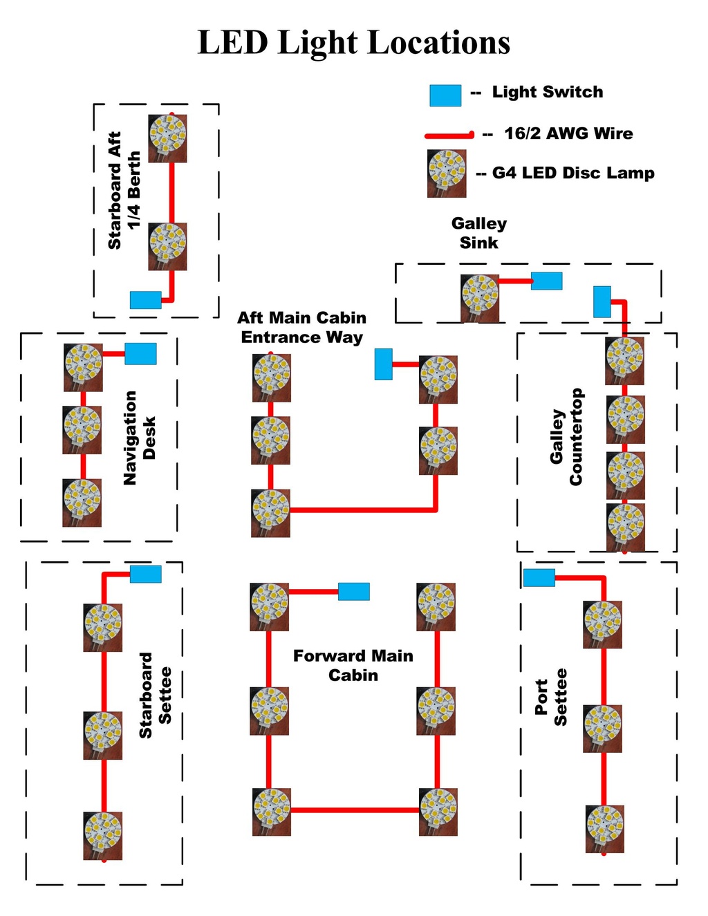
The original single lighting circuit was previously powered by one, 15 amp magnetic latch type circuit breaker. This circuit was separated into 8 branched independent circuits determined by the ON/OFF switch location - as the picture below illustrates.
Individual fused protective power was routed to each ON/OFF switch location using 16/2 AWG duplex wiring from a Blue Sea Systems 5026 ST Blade Fuse Block - as the picture below illustrates.
Next Step